Air Bearing Clock #1
This experimental clock was constructed to evaluate the practicality of supporting a pendulum from an air bearing. The air bearing that supports this pendulum is an off the shelf item from New Way Bearings. The main components are a 1" diameter air bearing mounted in a pillow block and a 1" diameter shaft.
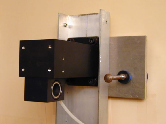
A pair of pillow blocks could have been used to construct a clock with a single pendulum rod, but because of alignment issues and cost, I chose to use a single bearing and a pair of rods. Axial motion of the shaft through the bushing is controlled by opposing magnets at each end of the rod. Measurements have not been made to determine if the opposing magnets cause any drag that changes the Q of the pendulum. The dual rod configuration provides some additional flexibility as to where the impulse can be delivered but also adds additional aerodynamic losses.
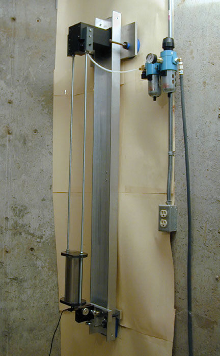
An overview picture of the clock (without the impulsing components) installed on a 10" thick poured concrete wall in my basement is shown at the right. The aluminum channel and the upper cross bar are attached to the wall with 3/8" expansion bolts that pass through isodamp (no bounce) rubber pads. The air bearing (bushing) is attached to the black anodized aluminum beam at the top of the channel.
The pendulum bob is a 3" dia by 8" tall steel cylinder from a Synchronome clock. The bob weighs approximately 13.5 lbs. The bob is currently supported by a pair of 3/8" threaded rods and a pair of Lexan plates. A MicroSet sensor is mounted on an adjustable support in order to make measurements of period and amplitude.
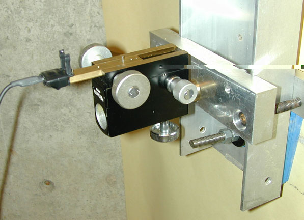
The images below show the air bearing in its pillow block on the left and the adjustable mounting for the MicroSet sensor on the right.
The clock worked well until the air bearing became contaminated with water due to a poor air delivery system that did not adequately deal with long term water removal.